
History of Remote Sensing: Multi-Spectral Scanner (MSS)
The MSS instrument has operated on all Landsat spacecraft. A simplified model of this optical-mechanical sensor appears in the next figure.
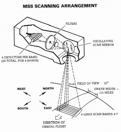
It gathers light through a ground-pointing telescope (not shown). The scan mirror oscillates side-to-side over an angular displacement of ± 2.89 degrees producing a beam width of 11.56 degrees that from an orbital altitude of 917 km ( about ~570 miles) covers a swath width (Angular Field of View or AFOV) across the orbital track of 185 km (115 miles). During a forward scan, which takes about 3.3 milliseconds, it sweeps a ground strip of about ~ 474 m (1555 ft) from one side of the track to the other. Reflected light gathered by this scan passes through an optical lens train, during which it is divides and passes through 4 filters that produce images in spectral bands at MSS 4 = 0.5 - 0.6 µm (green), MSS 5 = 0.6 - 0.7 µm (red), MSS 6 = 0.7 - 0.8 µm (photo-IR), and MSS 7 = 0.8 - 1.1 µm (near-IR). Light through each filter reaches its set of six electronic detectors (24 in all) that subdivide the cross-track scan into 6 parallel lines, each equivalent to a ground width of 79 m (259 ft). The mirror movement rate is such that, at the orbital speed of 26,611 kph (16,525 mph), after the return oscillation, the next forward swing produces a new path of 6 lines (79 x 6 = 474 m) just overlapping the previous group of 6 lines.
I-20: Individual scan lines are commonly visible crossing left to right on a Landsat image. Can you think of a technical reason why these may be seen? ANSWER
At each detector, the incoming light (photons) from the target frees electrons in numbers proportional to the number of photons striking the detector. These electrons move as a continuous current that passes through a counting system, which measures the quantity of electrons released ( thus, indicating radiation intensity) during each nine microsecond detection interval. Over that time interval the advancing mirror picks up light coming from a lateral ground distance of 79 m (259 ft). The detector thus images a two-dimensional, instantaneous field of view (IFOV), usually expressed in steradians, which denotes the solid angle that subtends a spherical surface and, in scanning, connotes the tiny area, within the total area being scanned, viewed at any instant of 0.087 mrad , which, at Landsat's orbital altitude of 917 km, means the effective resolution of the instrument is the 79 x 79 m2 described above. Each detector is then cleared of its charge to receive the next nine microsecond batch of electrons, and so the scanning continues through the full forward sweep. The onboard computer converts this succession of analog signals into digital values which the communication systems telemeters (sends) to Earth by radio.
For each band detector, the electronic signal from this IFOV results in a single digital value (called its DN or digital number, which, for the MSS, can range from 0 - 255 [28]). The value relates to the proportionally averaged reflectances from all materials within the each IFOV. Since the mix of objects on the ground constantly changes, the DN numbers vary from one IFOV to the next. Each IFOV is represented in a b & w image as a tiny point of uniform gray-level tone, known as a pixel (a contraction of "picture element") whose brightness is determined by its DN value. In a Landsat MSS band image, owing to a sampling rate effect in which there is some overlap between successive nine microsecond intervals, a pixel has an effective ground-equivalent dimension of 79 x 57 m (259 x 187 ft) but contains the reflectances of the full 79 m2 actually viewed .The average (but variable) number of pixels within a full scan line (representing 185 km) across the orbital track is 3240 (185 / 0.057). In order to image an equi-dimensional square scene, which requires 185 km of down track coverage, the average total number of lines to do this is set at 2340 (185 km/ 0.079 km). Each band image therefore consists of approximately (again variable) 7,581,600 (3240 x 2340)pixels - a lot to handle during computer processing.
We can use the continuous stream of pixel values to drive an electronic device that generates a uninterrupted light beam of varying intensity, which sweeps systematically over film to produce a b & w photo image. The resulting tone variations on the image are proportional to the DNs in the array. In a different process, we can display the pixels generated from these sampling intervals as an image of each band by storing their DN values sequentially in an electronic signal array. We can then project this array line by line on to a TV monitor, and get an image made of light-sensitive spots (also called pixels) of varying brightnesses.

Collaborators: Code 935 NASA GSFC, GST, USAF Academy Webmaster: Bill Dickinson Jr.
Primary Author: Nicholas M. Short, Sr. email: nmshort@epix.net
Contributor Information
Last Updated: September '99
Site Curator: Nannette Fekete
Please direct any comments to rstweb@gst.com.