
The Photographic Process; Photogrammetry
(Before beginning this long page, a review of page I-8 in the Introduction may be helpful.) Black and white (b & w) photographs start with exposing a light-sensitive film to incoming electromagnetic radiation (light), selected from the spectral range between ultraviolet through visible, and into the near infrared. The optical system of the camera focuses the light, reflected from the target, onto the focal plane (plane of focus). The film is held flat at the focal plane, and the light activates positions in the film area in the same spatial relation that the radiation photons had from the surfaces within the scene. The recorded exposure is a function of many variables, of which the three principal ones relate to the scene, the camera, and the film.:
1) The scene usually contains various objects that contribute their spectral character (reflected wavelengths) and intensities of the reflected radiation.
2) In the camera, we can vary the lens diameter, D, and the effective size of the aperture opening, d.
The aperture depends on the diaphragm width for admitting light. An open/shut shutter controls the duration of light admission. The optical characteristics of the lens vary the distance from the lens to the film (focal length, f) at which the focus is sharpest. This light-gathering system is adjustable for film response (ISO, formally ASA values);
3) In the film, its properties vary, e.g., which wavelengths it is most sensitive to, and under which conditions does it develop best as a negative and then printed.
For most cameras, the four variables that we normally adjust are:
1) the focus, by moving the lens back and forth, relative to the focal plane, so that the target image is in focus in the plane of the film;
2) the F-stop, defined as f/d, the focal length divided by the effective diameter of the lens opening. Typical values of the F-number are F/1 (the lens opening is the same size as the focal length), F/1.4, F/2 (the lens opening is half the focal length), and F/2.8 to F/22. The denominator increases by approximately the square root of 2 (1.414...), so that each decrease of F/d (i.e., denominator increases), leads to a decrease in the amount of light admitted by a factor of 2. Thus the F-number increases as the lens diameter decreases, and therefore we photograph dark scenes at low F-stops, e.g., F/2, and bright scenes at high F-stops, e.g. F/32.
3) the shutter speed (typically, in a sequence from 1/2000, 1/1000, 1/500, 1/250, 1/30, 1/15, 1/8, 1/2, 1/1, 2, 4 ...., in seconds), which controls film exposure times;
4) the film speed, i.e., the exposure levels over which the film responds. The ISO (ASA) rates film properties. High ISO numbers refer to "fast" film (high speed), e.g., ISO 1000, which requires less radiation (hence, a shorter exposure time or a smaller aperture) to achieve a given response. "Slow" film, e.g., ASA 64, requires a longer exposure or a larger aperture, but provides higher resolution. For aerial film, the AFS (Aerial Film Speed) is more commonly used.
One general equation for exposure is:
E = sd2t/(4f2)
where
(see Ch. 6 in Lillesand & Kiefer, 1994). Changes in any one or combination of these variables brings about variations in photo response characteristics. These differences can be favorable and we actuate them by adjusting one or more camera settings.
10-5: Given a camera in which you maintain control of the focal length, exposure time, and F-Stop (the old-fashioned or professional kind, not like those today that have automated the adjustment of these settings), and assuming it has a built-in light meter, enumerate the steps you would take in getting ready to take a picture of a) a nearby person, and b) a distant mountain range, on a sunny day and again near sunset. ANSWER Black and white film consists of a base or backing, coated by an emulsion composed of gelatin, in which are embedded tiny crystals of silver halides (commonly, Silver Chloride, AgCl) together with wavelength sensitive dyes. The dyes respond to radiation from segments of the electromagnetic spectrum, such as, ultraviolet, visible,and visible/near IR. Special films respond to photons from shorter or longer wavelengths; for example, X-ray film. When a number of photons strike a halide crystal, they knock loose electrons from some of the silver (Ag) atoms, ionizing them. The number of electrons thus activated depends on the brightness (intensity) of the radiation. We can control the part of the spectral range by using color filters over the lens. These filters admit radiation from limited segments of the spectrum. This process is a photochemical reaction which conditions the halide grains for later chemical change, forming an intermediate latent image (invisible but ready to appear when we develop it).
Developing begins by immersing the film in an alkaline solution of specific organic chemicals that neutralize the electrons and reduce Ag+ ions into minute grains of black silver metal. The number of such metallic grains in a given volume determines the film (negative) density. For parts of the emulsion receiving more light, the density (darkness) of the film is greater. In the developing process, we must stop the ion conversion at some point using an acidic stop bath. We remove any silver halides that remain undeveloped by chemical fixing Volumes in the thin film that saw little exposure (fewer photons) end up with minimal silver grains and thus appear as light and clear in the film negative. We can control and modify the development process, and hence relative densities in the negative, by changing such variables as solution strengths, developer temperatures, and times in each processing step.
Next, we must use the negative to make a separate, positive, black and white print, in which dark tones correspond to darker areas in the scene, and light tones to light areas. We do this during the printing process. A print (or a positive transparency) consists of an emulsion, backed (in a print) by paper. We pass white light through the negative onto the print material. Clear areas allow ample light to pass and strike the print, which produces high densities of dark (silver-rich) tones. Thus, the initial low levels of photons coming from the target (relative darkness) ultimately produce a print image consisting of many silver grains that make the areas affected dark. Bright target areas in turn, being represented by dark areas in the negative that prevent light from passing, are expressed as light (whitish to light gray) tones in the print (little silver, so that the whiteness of the paper persists). Once again, we can control the relative levels of gray, or increasing darkness, in the development process by changing the same variables as above, by modifying exposure times, by using print papers with specific radiation responses, and by using filters with different spectral responses (minimizing passage of certain wavelengths) or light transmission. Thus, we can choose different average tonal levels of the print, and, more important, we can adjust the relative levels of gray (tones) to present a pictorial expression, called contrast. Contrast determines whether a scene with variable colors and brightness appears flat or presents wide ranges of light-dark areas that aid in discriminating features. Contrast is the ratio of density to the logarithmic value of exposure. We can plot this ratio in the Hurter-Driffield (H-D) curve, which is a straight line with a slope angle for a range of exposures but becomes curved at high and low exposures.
We can expose b & w films under a condition that converts them into multispectral images. We do this by using color filters that pass-limited ranges of wavelengths (bandpass filters) during exposure. As we explained in the Introduction, a red filter, for example, passes mainly radiation in the red and nearby regions of the visible spectrum. Reddish objects produce high exposures that appear in dark tones on a negative and reappear as light tones in b & w prints or in red on color positive film. We describe why this is so different from the response of b & w film in the following paragraphs. Green appears as dark in a b & w multispectral image, representing the red region, and as dark or subdued green in a color multispectral version. We can project multispectral positive transparencies for different color bands using several color filters onto color print paper to produce natural or false color composites, as described in the Introduction.
How we use color film to produce color images involves some different concepts, although many of the same factors and mechanisms are still valid. Starting with the three additive primary colors, red, green, and blue, or the subtractive primary colors, yellow, cyan and magenta, we can make other colors by using the principles of either the color addition or the color subtraction process. Look at these diagrams:
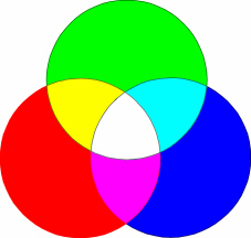
Additive Color Model
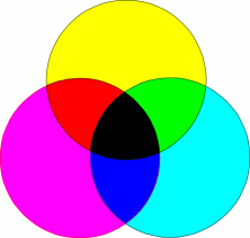
Subtractive Color Model
Color addition works when we superimpose the primary colors on one another. For example, if we shine a green light and a red light on the same spot on a white wall, we will see some shade of orange or yellow, depending on the relative intensity of the red and green illumination. If we add a third blue light to the spot, we will see white or a shade of gray. Computer displays work this way. To create a color, we can typically choose a number between 0 and 255 to indicate how much of each of the three primary colors we want. If our display board has sufficient memory, we will have 2553 (16,581,375) colors to choose from.
In subtractive color, we use filters to remove colors. For example, a yellow filter removes colors other than yellow, as do cyan and magenta filters. If one superimposes all three filters, little or no visible light gets through, so either black or dark gray results. By combining pairs of the subtractive primary colors, we can create each of the additive primary colors. Magenta and yellow produce red. What corresponds to cyan and magenta and yellow and cyan?
The principles of color subtraction apply to color-sensitized film. This film consists of emulsion layers containing silver chloride treated with light sensitive dyes, each responding to a limited wavelength range. These layers act as subtractive filters during development. Thus each layer of the film responds to different sections of the scene's spectrum. These layers are stacked, respectively, as follows: a blue-sensitive layer on the top, then a yellow filter layer (to screen out ultraviolet and blue from passing into the next layers; omitted from the diagrams below), and finally, green- and red-sensitive layers.
From F.F. Sabins, Jr., Remote Sensing: Principles and Interpretation. 2nd Ed., © 1987. Reproduced by permission of W.H. Freeman & Co., New York City.
Referring to the above diagram, when a shade of red passes through a color layer sensitized to cyan (a blue-green, the complementary color to red; the sum of any primary color and its opposing complement always equals white), its absorption activates the dye/silver grains in that layer to produce, in a negative, cyan tones in areas associated spatially with reddish objects in the scene. In color film, the three subtractive color layers stack together (a fourth serves a special purpose, described below) on top of a clear base. To guide you in reasoning through production of other colors, check this schematic diagram:
From F.F. Sabins, Jr., Remote Sensing: Principles and Interpretation. 2nd Ed., © 1987. Reproduced by permission of W.H. Freeman & Co., New York City.
Thus, in a similar manner, light from a blue subject reacts with the yellow layer to produce a yellow shade (red and green make this complementary color) for its area on the negative. To test your understanding, from the diagram, set up the response for green objects (magenta, a bluish-red, is a mix of red and blue). There is an obvious rule working here:
10-6: To test your understanding, from the above diagram, you set up the response for green objects (magenta, a bluish-red, is a mix of red and blue). Also look at the diagram just below. No doubt you can see an obvious rule working here: devise it. ANSWER
From F.F. Sabins, Jr., Remote Sensing: Principles and Interpretation. 2nd Ed., © 1987. Reproduced by permission of W.H. Freeman & Co., New York City.
As evident in the diagram, each primary color activates the layer containing the subtractive color opposite it . Several other rules or observations apply:
1) A given primary color does not directly activate the other two film layers.
2) Note that yellow + magenta = red. The red is common to each of these subtractive colors, with blue and green being filtered out. The same rationale applies to the other two combinations of subtractive colors.
3) White light exposes all three subtractive layers in the negative. The sum of these three layers (the center of the color diagram on the right) on a positive is black. Conversely, black (absence of light) objects produce a clear (not colored) area in the three layers of film
4) We must insert a fourth, special yellow filter layer below the yellow layer, because the dyes in the red and green sensitive layers below are also sensitive to blue, which this filter layer screens out and then dissolves away during developing.
To comprehend how to make a color print, follow this set of arguments: when white light passes through the color negative to initiate the printing, cyan areas transmit that light through the cyan layer of the print film (called the positive or reversal film) but not through the magenta or yellow areas, exposing each so that it assumes its color. Since the sum of yellow and magenta is red, during development, the print film is red in the areas that are cyan in the negative. The same line of reasoning applies to the magenta and yellow areas on the negative, with green and blue resulting. If the negative has yellow and magenta occupying the same areas on the two superimposed layers, the results will be green + green? = yellow, and so forth, for other non-primary colors. To reiterate, the blue from the cyan of the negative activates, first the yellow layer (sensitive to blue which is absorbed) and then the magenta layer (sensitive to green), but the cyan bottom layer is not sensitized by the cyan light (passes through), becoming clear during development. We can tailor this statement for each of the other two negative colors.
We can generate color transparencies by a similar color-reversal technique but without the need for a negative. First, we develop the exposed transparency film to cause it initially to act as a negative image (converting the sensitized silver chloride/dyes to color grains) in each of the three color emulsion layers. We then re-expose the film to white light to develop any remaining silver halide . This latent positive image is then chemically coupled or combined with color dyes to produce a positive color image in each layer. Next, we treat the film in a bleach, which, without affecting the dyes, converts silver into soluble salts and removes unused dye couplers, while removing the initial yellow filter layer. A red subject forms a magenta and a yellow image pattern on the green- and blue-sensitive layers. When white light projects through this transparency, yellow and magenta layers absorb blue and green respectively, allowing red to appear in the projected image where red should be spatially. (Likewise for the other colors.)
Other systems of color production have been devised. One mentioned briefly here is the IHS system, in which:
This system is sensitive to controllable transformations (computer-aided) that optimize and enhance color representations.
Let's move now from the spectral part of photogrammetry to the spatial part. Scale, mentioned before, is just the comparison of the dimensions of an object or feature in a photo or map to its actual dimensions in the target. We state scale in several ways, such as, "six inches to the mile", "1/20,000", and, most common "1:2,000". These mean that one measurement unit in the numerator (image or map) is equivalent to the stated number of that unit in the denominator (scene). Thus, 1:2,000 simply states that one of any length unit, such as an inch, in the photo corresponds to 2,000 inches on the ground or air (cloud). Or, one cm is equivalent to 20,000 cm. "six inches to the mile" translates to six inches in the photo represents 63,360 (5,280 ft x 12 in/ft) inches in the real world, but we can further reduce it to 1:10,560, because six and 63,360 are divisible by six. Note that, if we enlarge or contract a photo of a given scale, say by projection as a transparency onto a screen, then one inch on the screen no longer corresponds to the same denominator number but now represents some other scale determined by the magnification factor. However, the effective resolution, the area covered, and the relative details remain the same.
We determine the scale of the aerial photo, expressed as its Representative Fraction (RF) by the height of the moving platform and by the focal length of the camera, according to this equation: RF = f/H*, where H* = H - h, with H = height (elevation with reference to sea level) of the camera and h is the height of a reference point on the surface, so that H - h is the distance between the platform and the point (assuming a flat ground surface; in rugged terrain, scale in effect varies with the elevations). We can also show that RF is also proportional to resolution and distance ratios, as given by RF = rg/rs = d/D, where rg is ground resolution (in line pairs per meter; see below) and rs is the sensor system resolution (in line pairs per millimeter); d is the distance between two points in the photo and D is the actual distance between these points on the ground (the definition of scale).
Several more questions will help to master these ideas.
10-7: A map has a scale of 9.0 inches to the mile. What is the denominator of the RF? ANSWER
10-8: Two points appear on a map 1.75 inches apart. The actual horizontal ground distance between the two points is 1108.0 meters. What is the denominator of the scale fraction (RF) for this map? ANSWER
10-9: Points A and B are 2.2 inches apart on a map having a RF = 1/20000. They are 6.83 inches apart on an airphoto. What is the scale of the airphoto? ANSWER
10-10: A vertical airphoto is taken from a flying height of 5000 ft relative to the ocean with a camera having a focal length of 6 inches. The flat surface is 1000 ft above sealevel. What is the RF for the resulting photo? ANSWER
10-11: An aerial camera has a 9 1/2 inch square film format and a 6 inch focal length lens. What must the flying height (in meters) be to obtain a scale (RF) of 1/2000? ANSWER
We can elucidate the roles of f and H* further with the aid of the next diagram, which, although not strictly correct in terms of optics and simplified to two dimensions, does allow us to visualize the effects of changing focal length and platform height:
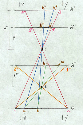
Lines such as 1-1" or a-a' are light rays passing through the lens L. G is the ground. A' is at the focal plane (holding the film) for a focal length of f ', and A" is the shift of this plane to a new value of f ". A"' is the location of the focal plane for a case in which the lens, L, is now at a lower elevation. A line on the ground, a-b, passing through lens, L, is focused on plane A', such that, it has a film dimension of b'-a' (note that it is reversed in position but this does not matter because we can turn over a transparent negative). When we lengthen the focal length to f" to bring the focus onto A", b'-a' expands to b"-a". Look next at what happens when we lower the camera (and airplane) to the A"' position: a-b in this new arrangement (where L, the lens location relative to the film is the same distance as case 1, so that the focus, or focal length, is once more f ', i.e., f"' = f'), now is expressed by b'''-a''', which for these conditions is even longer than b"-a". In these situations the frame size of the film (x-y in the two dimensional simplification) remains the same. Therefore, when x-y is at the A" location, the fraction of the scene imaged decreases by the loss of the outer parts and b"-a" occupies a larger segment of it. In the A"' case, the size of film needed to display all of 1-2 is even greater, so that x-y now encloses even less of the scene. The A"' image, held to the x-y limit, is larger scale than an A' image and the A" image is also larger. Keep in mind that the dimensions shown on the line G are ground-sized, whereas those in A', A", and A"' are film-sized, reduced relative to ground distances by the scales of the photographs.
We summarize these relations in a mnemonic: long is large/low is large and large is small. We interpret it as follows: the scale is larger (denominator becomes smaller) as we lengthen the focal length or as we lower the platform. A large(r) scale image covers a small(er) ground area (with increased resolution). To appreciate how scale affects scene content, you may return to the various photos that we brought on-line in the previous page. The scale of each is printed alongside it.
Resolution has a popular meaning but is best defined in a technical sense. We normally think of resolution as the ability to separate and distinguish adjacent objects or items in a scene, be it in a photo or real life. We specify the resolution in terms of the smallest features we can discriminate. But, contrast influences resolution. If two items are the same color, they may be hard to separate, but if they are sharply different in color, tone, or brightness, we can identify them more easily. Shape also is a factor. So, a rigorous definition of resolution relies on the ability to separate adjacent alternating black and white thin lines in a target. The resolution of a film is determined in a laboratory by photographing placard sized charts containing black lines with different spacings on a white background (or the reverse). Then, the resolution is the smallest spacing, in which we can discriminate pairs.
We can place such a target in a scene (for example, painting black lines with different spacing on a concrete airport runway or road) to determine resolution for aerial conditions. Ground resolution is then the number of black/white line pairs within some width (normally one meter) that we can just discern in aerial photos taken at a particular height. Depending on the camera, film resolving power, and platform height (the system), in the photo, the pair will either blend visually (not resolvable) or can be distinguished. We express system resolution, rs, (in which we combine the effects of sensor and film factors ) in line pairs/mm within the print. A formula for ground resolution, rg, (in line pairs/meter), applicable to just separable ground lines, is:rg = f x rs/H. A typical example is a case where the lens focal length is 150 mm, the system resolution is 60 line pairs/mm, and the height is 3,000 meters, so that Rg is 3 line pairs/meter. From the relation 1 line pair/rg = width on ground of 1 line pair, this width is 0.33 m (each line is half that value). This means that the airborne camera can resolve an object on the ground that has a dimension of 0.165 m (about 6.5 inches), if it contrasts with its surroundings, using a film of appropriate resolving power. If the aircraft were flying higher, the camera could not detect this sized object.
10-12: Given a camera with the focal length of 9 inches, capable of a photo resolution of 15 line-pairs per millimeter, when flown at an altitude of 12000 ft, what is the equivalent resolution on the ground. ANSWER
10-13: What is the photo (system) resolution obtained when a camera with focal length of 120 mm is flown at an altitude of 6000 meters; the line-pair in a calibration target on the ground has a spacing of 4 line-pairs/m. ANSWER
Resolution in film (negatives and prints) is governed, in part, by the size distribution of the silver grains. In LandsatÕs Multispectral Scanner/Thematic Mapper (MSS/TM), and other electronic sensors, image resolution ties closely to the size of the pixels or to the dimensions of individual detectors in the arrays of Charge-Coupled Detectors (CCDs), such as on SPOT. At first thought, it would seem that we cannot resolve objects smaller than the ground dimensions represented in an individual pixel/detector. However, if the spectral characteristics of a subresolution spot on the ground are sufficiently different from surrounding areas, they can affect the average brightness of the pixel so that the spot is visible in the image. An example of this are roads that are narrower than a 30 m (98 ft) TM pixel, yet are quite visible in a TM image.
In an aerial photo, when we view features at ground points off the principal point (optical center, usually at nadir or normal to a flat surface), that is, along slant directions, they may appear to lean away from the center, especially if they are tall (e.g., buildings) or have high relief. This distortion is worse if the aircraft flies low to acquire large scale photos. This is one type of displacement, and is evident near the edges in the 1:4,000 aerial photo of a neighborhood in Harrisburg, shown on page 10-1. We consider other modes of displacement, such as apparent lateral movements of image points along slopes of differing angles, in Section 11, which explores 3-D aspects relevant to stereo viewing and photogrammetric mapping.
We can fly aerial photo missions at any time during the day, but they usually occur between about 10:00 AM and 2:00 PM (in summer to avoid afternoon storms). Typically, the aircraft traverses the region to be photographed along back-and-forth flight lines and acquires pictures at intervals that allow about 50% overlap between successive photos and 20% to 50% sidelap between lines. The camera usually mounts below the plane, near its nose. Film in the camera advances automatically at time intervals that are synchronized with the speed of the aircraft. Especially in color photos, but also in black and white photos, blue and ultraviolet light that is scattered by the atmosphere may degrade the film image. We can reduce this degradation by using a haze filter that absorbs the ultraviolet and the very shortest visible blue wavelengths.
NASA has a stable of support aircraft that operate various sensors, including cameras, to gather ground reference data for remote sensing experiments (see Section 13 which discusses this). An example of a small-scale image (about 1:150,000) obtained during a U-2 flight, which operated at an altitude of about 18,000 m (59,000 ft) over Utah (resolution about 5 meters), closes this section on aerial photography.
For anyone interested in viewing more aerial-type photos, including perhaps one of a home region, consult the on-line Net Home Page called "Terraserver", sponsored by Microsoft. Aerial imagery, either individual photos or sections of orthophotoquads, of selected large parts of the United States, has been digitized from data collected by the U.S. Geological Survey. Their resolution ranges from less than 2 to about 12 meters. Imagery taken with the KVR-1000 camera (resolution: 2 meters) flown on several Russian satellites shows regions in the rest of the world, mainly in Europe. They market these data worldwide as part of their SPIN-2 program. All photos are black and white.
Of course, the principles we have been applying in these two pages to aerial photos pertain in many respects to space imagery as well. Mapping once done primarily with air photos can now be done almost as well with space products. The main drawback is resolution, and that limitation is rapidly disappearing with the declassification of high resolution military imagery and with the ever-improving resolution capability of satellites now being flown or on the drawing boards for the foreseeable future. As we shall see in the next section, the ability to gather data from space that pertain to three-dimensional surface variations allows the mapping community to essentially duplicate all the advantages once exclusive to air-based photography.

Primary Author: Nicholas M. Short, Sr. email: nmshort@epix.net
Collaborators: Code 935 NASA GSFC, GST, USAF Academy
Contributor Information
Last Updated: September '99
Webmaster: Bill Dickinson Jr.
Site Curator: Nannette Fekete
Please direct any comments to rstweb@gst.com.